|
Constructing the floor grid for a picture
We can put all the theory together to create a foreshortened floor grid from a plan grid to support any picture, those of an artistic temperament may prefer to
mould the plan by eye:
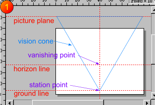
 1 Create two horizontal guides to
represent your horizon (eyeball height), ground line and a vertical one for central line of sight. These in turn define the station point and primary vanishing point by their intersections. Now for the clever bit,
a superimposed plan view. From the station point construct a regular three sided polygon with one apex at the station point such that all sides equal the width of your
picture. This marks the angle of vision with the picture plane marked along the top. Don't worry that it seems in an odd position. 1 Create two horizontal guides to
represent your horizon (eyeball height), ground line and a vertical one for central line of sight. These in turn define the station point and primary vanishing point by their intersections. Now for the clever bit,
a superimposed plan view. From the station point construct a regular three sided polygon with one apex at the station point such that all sides equal the width of your
picture. This marks the angle of vision with the picture plane marked along the top. Don't worry that it seems in an odd position.
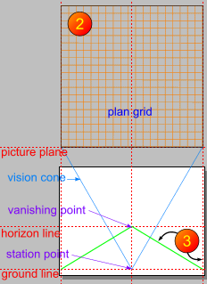
 2 Now construct a square plan grid above it
as indicated by blending two horizontal lines the width of the picture and the same distance apart, cloning the blend and turning it 90 degrees to form a square grid. Now we need to translate the grid into a
foreshortened one to fit into the picture, by constructing its foreshortened outline and moulding it into place. 2 Now construct a square plan grid above it
as indicated by blending two horizontal lines the width of the picture and the same distance apart, cloning the blend and turning it 90 degrees to form a square grid. Now we need to translate the grid into a
foreshortened one to fit into the picture, by constructing its foreshortened outline and moulding it into place.
3 Run two vertical guides to mark the edges of the plan grid. The intersections of these with the ground line will pinpoint the front
corners of the foreshortened grid since they are also on the picture plane. Since we are dealing with single point perspective the sides of the foreshortened grid will lie on
lines joining these to the central vanishing point, shown left in green.
|

