|
VARIATIONS ON SKEW AND ROTATION VALUES Earlier, it was mentioned that the three
isometric axes are at equal angles (120 degrees) to one another. 
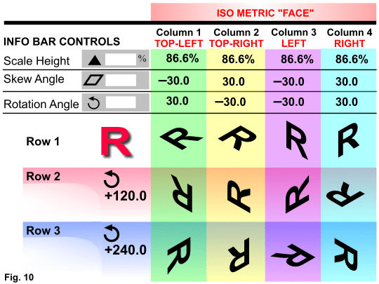
Fig. 10
shown above, diagrams various combinations of minus and positive Skew and Rotation angles. Rows 2 and 3 depict how the orientation of an object is changed as it is rotated about the axes. Row 2
shows what happens when the "R" directly above it in Row 1 is rotated an additional 120 degrees. Row 3 shows the results when the "R" above it in Row 1 is rotated
240 degrees (which is the same as rotating an "R" directly above it in Row 2 by 120 degrees). NOTE: As a shortcut, you can enter the NET Rotation angle. For example: for the "R" in Row 2 - Column 2, use a rotation of 90 (-30
+ +120) or for the "R" in Row 3 - Column 4, use a rotation of 270 (+30 + +240).CONSTRUCTING AN ISOMETRIC AXIS
Once an object as been transformed into a face, it will probably need to be given a depth. Other vector and 3-D applications accomplish
this by an "extrusion" process. Although Xara X does not have a designated extrusion function, it has the essentials to accomplish the same thing.
The depth of an object is projected (extruded) along an isometric axes. The isometric basics on a previous page mention that two of the axes are 30 degrees from a horizontal line. The other is
perpendicular to a horizontal line. In Xara its relatively easy to draw lines representing an isometric axis at a prescribed length.  Fig. 11 using the Freehand Tool (F3), press and hold Ctrl and Alt, click and drag a line the desired direction and approximate distance, and
release the mouse. Then, using the Shape Editor tool (F4), select the axis' last end-point, and in the Infobar's Line Length field enter the length of the axis and press Enter. Fig. 11 using the Freehand Tool (F3), press and hold Ctrl and Alt, click and drag a line the desired direction and approximate distance, and
release the mouse. Then, using the Shape Editor tool (F4), select the axis' last end-point, and in the Infobar's Line Length field enter the length of the axis and press Enter.
 As shown in Fig. 12 it is important to note you can use the Shape Editor Tool
at anytime. Select the last end-point of an axis, and the Infobar will tell you its absolute Line Angle and Line Length. As shown in Fig. 12 it is important to note you can use the Shape Editor Tool
at anytime. Select the last end-point of an axis, and the Infobar will tell you its absolute Line Angle and Line Length.
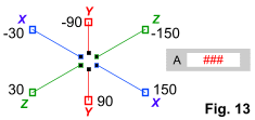
 Fig. 13 shows Xara's six absolute Line Angle values for a segment on an isometric axis. Fig. 13 shows Xara's six absolute Line Angle values for a segment on an isometric axis.
Also, any two-point line segment can be made into an isometric axis by
selecting its last end-point with the Shape Editor Tool, entering one of these six angles in the Infobar, and pressing Enter. There may be times when it is advantageous to keep all extrusions
axes so, rather than deleting then, use them as "construction lines" so revisions to isometric objects can more easily be made. In this situation the axes can be drawn on a designated layer or given a
outline width of None so they are temporarily "hidden" . |

